
For three decades, data center thermal management operated on a straightforward thermodynamic assumption: heat generated by silicon processors could be extracted by forcing chilled air through aluminum heatsinks, channeling the exhausted heat into hot-aisle containment corridors, and cycling it through computer room air handlers (CRAHs). Even during the initial surge of enterprise deep learning—when high-density server chassis packed eight air-cooled Nvidia H100 GPUs drawing 10.2 kW per rack—facility engineers managed thermal loads by deploying high-static-pressure blowers, perforated raised floors, and localized rear-door heat exchangers (RDHxs).
The arrival of Nvidia's Blackwell architecture and the flagship **GB200 NVL72** has rendered that assumption entirely obsolete. The GB200 NVL72 is not an incremental server upgrade; it is a single, structurally unified 72-GPU accelerator. By interconnecting 36 Grace CPUs and 72 Blackwell B200 GPUs across nine dedicated NVLink Switch trays via a 5th-generation NVLink copper spine (delivering 130 TB/s of aggregate bisection bandwidth), Nvidia concentrated an unprecedented **120 kW to 132 kW of thermal energy** into a single 42U/48U rack footprint.
At Beyond Ambition, our DevOps & Cloud Infrastructure Consulting Teams and AI Engineering & LLM Integration Practice design and orchestrate computing environments for high-throughput client platforms. From building real-time algorithmic risk engines for Atmos Funded to optimizing distributed inference pipelines for IonicX AI, navigating the physical realities of modern hardware infrastructure is fundamental to sustaining peak system availability. In this architectural teardown, we analyze the thermodynamics that broke air cooling, dissect the internal mechanics of direct-to-chip copper microchannel cold plates, evaluate Coolant Distribution Unit (CDU) hydraulics, examine blind-mate quick disconnect engineering, and implement production telemetry to detect micro-leaks before they compromise mission-critical silicon.
1. The 100kW+ Wall: Why High-Density AI Clusters Shattered Air Cooling
To understand why air cooling fails at 120 kW rack density, one must evaluate the physical transport properties of air versus liquid. The rate of convective heat transfer is governed by Newton's law of cooling: $Q = h \cdot A \cdot (T_{\text{surface}} - T_{\text{fluid}})$, where $h$ is the convective heat transfer coefficient, $A$ is the wetted surface area, and $(T_{\text{surface}} - T_{\text{fluid}})$ is the thermal delta between the silicon package and the cooling medium.
Air is an exceptionally poor heat transfer medium. Standard sea-level air has an isobaric specific heat capacity ($C_p$) of approximately $1.005 \text{ kJ}/(\text{kg}\cdot\text{K})$ and a density of roughly $1.204 \text{ kg}/\text{m}^3$, yielding a volumetric heat capacity of only $1.21 \text{ kJ}/(\text{m}^3\cdot\text{K})$. By contrast, liquid coolant (such as treated water or a 25% propylene glycol mixture) possesses a specific heat capacity of $4.184 \text{ kJ}/(\text{kg}\cdot\text{K})$ and a density of approximately $1,000 \text{ kg}/\text{m}^3$—giving it a volumetric heat capacity of roughly **$4,180 \text{ kJ}/(\text{m}^3\cdot\text{K})$**, more than **3,400 times higher than air**.
- **Volumetric Airflow Impracticability:** Dissipating 130 kW of thermal dissipation solely through air with a realistic 15°C temperature rise would demand continuous airflow exceeding 14,000 cubic feet per minute (CFM) per rack. Channeling that volume through a standard 24-inch rack frame creates extreme static pressure drops that standard chassis fans cannot overcome.
- **Parasitic Fan Power Overhead:** Overcoming high static pressure requires industrial-grade fans spinning at 15,000+ RPM. At 120 kW rack loads, fan power consumption alone would consume 25 kW to 35 kW per rack—wasting more than 20% of facility electrical supply strictly on moving air, devastating the data center's Power Usage Effectiveness (PUE).
- **Acoustic & Structural Limits:** Racks operating air-cooling fans at maximum static velocity produce sound pressure levels exceeding 98 dBA, breaching OSHA workplace safety thresholds and vibrating delicate optical transceiver interfaces in neighboring network switches.
- **Silicon Thermal Runaway:** Under sustained FP4/FP8 GEMM matrix multiplication workloads, each Blackwell B200 GPU draws up to 1,200W. Air-cooled heatsinks exhibit a thermal resistance ($R_{\text{th}}$) of 0.05 to 0.08 K/W. At 1,200W, the temperature delta from heatsink to ambient would exceed 60°C. Added to a 25°C datacenter ambient temperature, the silicon die temperature ($T_j$) instantly exceeds the 85°C thermal throttling ceiling, inducing catastrophic clock degradation.
| Thermodynamic Parameter | Forced Air Cooling (Legacy) | Direct-to-Chip Liquid Cooling (GB200) |
|---|---|---|
| Volumetric Heat Capacity | ~1.21 kJ/(m³·K) | ~4,180 kJ/(m³·K) (>3,400× advantage) |
| Heat Transfer Coeff (h) | 20 – 100 W/(m²·K) | 5,000 – 15,000 W/(m²·K) |
| Max Sustainable Rack Density | 12 kW – 18 kW per rack | 120 kW – 150+ kW per rack |
| Parasitic Cooling Power Overhead | 18% – 30% of total rack power | 3% – 5% of total rack power (pumps) |
| Facility PUE Benchmark | 1.40 – 1.65 (mechanical chillers) | 1.06 – 1.09 (free cooling / dry towers) |
| Coolant Temperature Allowance | Requires 18°C – 24°C chilled air | Supports 32°C – 45°C warm-water inlet |
2. Direct-to-Chip Mechanics: Copper Microchannels and Heat Flux at the Silicon Die
To capture heat before it dissipates into the chassis interior, the GB200 NVL72 mounts custom-engineered microchannel cold plates directly on top of each processor package. In a Blackwell B200 package, the thermal challenge is magnified by advanced packaging: two reticle-sized silicon dies are linked by a 10 TB/s NV-HBI (Nvidia High-Bandwidth Interface) over a TSMC CoWoS-L (Chip-on-Wafer-on-Substrate with Local Silicon Interconnect) substrate, framed by eight high-stack HBM3e memory packages offering 192 GB of capacity at 8 TB/s bandwidth.
Heat generation across this multi-die package is non-uniform. While the HBM3e memory stacks generate relatively diffuse thermal footprints, the compute logic and tensor execution cores generate localized heat flux exceeding **$100 \text{ W}/\text{cm}^2$**—comparable to the heat flux observed at the surface of a nuclear reactor fuel rod. To dissipate this without hot-spotting, the cold plate's internal chamber features micro-machined copper cooling fins with channel widths under 50 microns.
- **Microchannel Boundary Layer Disruption:** As coolant flows through the microscopic copper channels, it disrupts the thermal boundary layer that normally forms over smooth surfaces. The microscopic fin structures force high fluid shearing, transforming laminar flow into boundary-layer turbulence and driving the convective heat transfer coefficient ($h$) above $10,000 \text{ W}/(\text{m}^2\cdot\text{K})$.
- **Thermal Interface Materials (TIM):** Traditional silicone-based thermal greases suffer from 'pump-out' and dry-out under aggressive thermal cycling (rapidly shifting between idle 150W and peak 1,200W). High-density liquid cold plates utilize advanced Phase Change Materials (PCM) or indium foil liquid-metal alloys with thermal conductivities exceeding $60 \text{ W}/(\text{m}\cdot\text{K})$, minimizing contact resistance ($R_{\text{interface}}$) between the IHS and cold-plate base.
- **Direct Memory Cooling:** In the GB200 compute tray, the cold plate is not limited to the main GPU dies. An integrated, precision-machined cold-plate skirt extends across all eight adjacent HBM3e modules and the onboard voltage regulator modules (VRMs/DrMOS), preventing thermal runaway on power delivery components supplying hundreds of amperes at sub-1.0V core voltages.
3. Hydraulic Topology: In-Rack CDUs, Primary vs. Secondary Loops, and Hydraulic Balancing
A reliable liquid-cooled AI datacenter never circulates facility cooling tower water directly through sensitive server electronics. Instead, the GB200 NVL72 utilizes a dual-loop hydraulic topology separated by an in-rack or in-row **Coolant Distribution Unit (CDU)**, as standardized by the Open Compute Project (OCP) Advanced Cooling Facilities specifications.
The **Primary Facility Water System (FWS)** connects the CDU to the data center's external evaporative cooling towers, dry coolers, or central chilled water plant. The **Secondary Loop (Technology Cooling System / TCS)** is a hermetically sealed, ultra-clean internal circulation circuit that delivers treated fluid directly to the 18 compute trays and 9 NVLink Switch trays inside the NVL72 rack.
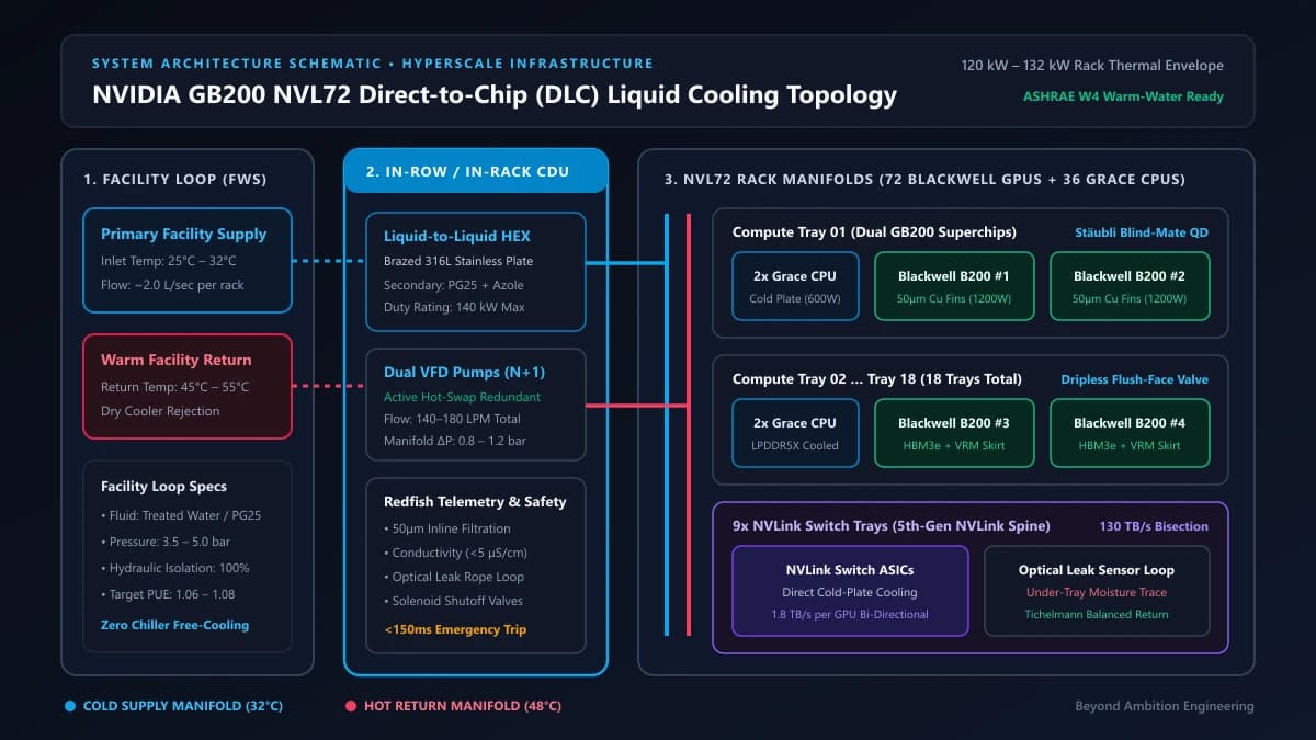
- **Brazed Stainless Plate Heat Exchanger (HEX):** Inside the CDU, an industrial counter-flow brazed plate heat exchanger transfers up to 140 kW of thermal energy from the secondary loop into the facility primary loop without permitting cross-contamination of fluids.
- **Secondary Coolant Chemistry:** The secondary loop circulates deionized water treated with a 25% to 35% concentration of inhibited propylene glycol (PG25/PG35) combined with azole copper corrosion inhibitors and non-oxidizing biocides. This maintains a stable pH between 7.5 and 9.0, preventing galvanic corrosion across copper cold plates, brass fittings, and aluminum chassis structural components.
- **N+1 Redundant Variable-Frequency Pumps:** The CDU houses dual variable-frequency drive (VFD) centrifugal canned-motor pumps operating in active $N+1$ or $2N$ redundancy. If a primary pump motor develops bearing wear or electrical failure, the standby pump instantly ramps up within 200 milliseconds to preserve hydraulic head pressure.
- **Hydraulic Balancing & Tichelmann Reverse-Return:** In a 48U rack, fluid entering a vertical manifold naturally favors the path of least resistance (Tray 01 at the bottom), risking severe flow starvation at Tray 18 at the top. The GB200 NVL72 integrates a reverse-return (Tichelmann) piping loop and precision orifice restrictors to ensure identical pressure differentials ($\Delta P \approx 0.8\text{ to }1.2\text{ bar}$) across all 18 compute trays, ensuring uniform 2.2 LPM flow per GPU cold plate.
4. Blind-Mate Quick Disconnects: Eradicating the 'Sticky QD' and Mechanical Failure Modes
In production hyperscale environments, serviceability is as critical as thermal efficiency. Enterprise operators cannot drain an entire 130 kW hydraulic loop containing tens of liters of glycol solution merely to replace a failed DIMM, boot drive, or power supply module. To achieve seamless field-replaceable unit (FRU) maintenance, compute trays interface with vertical rack manifolds using **blind-mate Quick Disconnect (QD) couplings**, engineered by manufacturers such as Stäubli and Eaton.
Unlike manual quick disconnects requiring two hands to collar and release, blind-mate couplings engage and disengage automatically as the compute tray slides into or out of the rack chassis on heavy-duty telescoping guide rails. Achieving this at high hydraulic pressures requires overcoming significant mechanical challenges:
- **Dual Flush-Face Shutoff Valves:** Both the male tray-side probe and female manifold-side socket incorporate flat, spring-loaded poppet seals. Upon disengagement, internal spring tension snaps both valves shut simultaneously, resulting in a spillage volume under 0.05 milliliters (less than a single droplet of moisture).
- **Overcoming the 'Sticky QD' Phenomenon:** Early liquid-cooled test clusters suffered from mechanical jamming, where micro-particulate debris or degraded ethylene glycol polymers coated valve surfaces, causing valves to stick partially open during extraction. Modern GB200-certified QDs feature electropolished 316L stainless steel internals and continuous 50-micron inline particulate filtration to ensure fluid seal integrity over thousands of insertion cycles.
- **Mechanical Tolerance & Self-Centering Pins:** Thermal expansion and contraction over 120 kW load swings can cause chassis sheet metal to warp by 1.0 to 1.8 millimeters. Blind-mate QD assemblies incorporate spherical floating mountings and hardened steel chamfered guide pins that absorb up to ±2.5 mm of axial and radial misalignment, eliminating shear stresses on O-ring gaskets.
Shipping Next.js 16, Multi-Agent RAG, or High-Concurrency Microservices?
Partner with Beyond Ambition Limited (NZBN 9429053304834) for fixed-milestone delivery and 99.99% SLA guarantees.
5. Operational Telemetry & Leak Mitigation: Optical Ropes, Differential Pressure, and Interlocks
Deploying pressurized liquid lines directly above high-voltage 48V/54V copper power busbars carrying thousands of amperes of DC current constitutes an obvious operational hazard. The GB200 NVL72 implements an automated, multi-tiered defense-in-depth leak detection and mitigation system orchestrated through hardware interlocks and the Redfish platform management protocol.
- **Optical Sensing Ropes & Conductive Trays:** Beneath every manifold coupling, blind-mate QD interface, and compute tray floor lies a continuous optical fiber or conductive polymer leak detection cable. Even a single droplet of conductive fluid spanning the sensor track alters electrical impedance or optical refraction, triggering an instantaneous hardware interrupt to the tray's Baseboard Management Controller (BMC).
- **Differential Pressure (ΔP) Micro-Leak Detection:** In-rack CDUs continuously sample supply and return pressure transducers at 100 Hz. If the mathematical delta between expected pump head and observed manifold pressure deviates by more than 0.15 bar within a 200 ms rolling window, the CDU identifies a fluid loss anomaly before physical moisture reaches external chassis surfaces.
- **Inline Electrical Conductivity Monitoring:** Continuous inline sensors measure the secondary loop's electrical conductivity. Pure deionized water exhibits conductivity below 1.0 µS/cm. If dissolved mineral ions or galvanic corrosion products push conductivity above 20 µS/cm, the CDU alerts operators that the fluid has become electrically conductive and requires deionization resin bed regeneration.
- **Sub-150ms Emergency Trip Interlock:** Upon confirmation of an active leak or catastrophic pressure collapse, the CDU initiates an automated safety protocol: fast-acting solenoid isolation valves sever supply and return flow to the affected manifold branch within 150 milliseconds, CDU circulation pumps ramp to idle, and an emergency signal is transmitted to the power shelf to gracefully drain PCIe/NVLink traffic and trip rack breaker coils before electrical shorting can occur.
6. Production Telemetry: Monitoring CDU Hydraulics and Thermal Health with Python and Redfish
In an enterprise infrastructure deployment, real-time observability of fluid dynamics is as important as monitoring GPU utilization and CUDA memory allocation. Below is an asynchronous Python telemetry collector that interfaces directly with an in-rack CDU Baseboard Management Controller (BMC) using the standardized DMTF Redfish Thermal and Cooling Loop API. It continuously samples hydraulic pressure drops, coolant supply flow rates, and optical leak sensor loops, exporting Prometheus metrics and tripping safety interlocks when anomalies occur:
"""
NVIDIA GB200 NVL72 — In-Rack CDU Telemetry & Safety Interlock Daemon
Collects hydraulic metrics, monitors differential pressure, and triggers automated shutoff.
Compliant with DMTF Redfish CoolingLoop and ThermalMetrics Schema (DSP2055).
"""

import asyncio
import logging
from typing import Dict, Any, Optional
import httpx
from pydantic import BaseModel, Field

logging.basicConfig(level=logging.INFO, format="%(asctime)s [%(levelname)s] %(message)s")
logger = logging.getLogger("cdu_telemetry")

class CDUTelemetry(BaseModel):
    rack_id: str
    supply_temp_celsius: float
    return_temp_celsius: float
    supply_pressure_bar: float
    return_pressure_bar: float
    flow_rate_lpm: float
    fluid_conductivity_us_cm: float
    leak_detected: bool
    pump_status: str

    @property
    def differential_pressure_bar(self) -> float:
        """Calculate secondary loop pressure drop (Delta-P) across compute trays."""
        return round(self.supply_pressure_bar - self.return_pressure_bar, 3)

class CDUMonitorClient:
    def __init__(self, bmc_ip: str, auth_token: str, rack_id: str = "RACK-NVL72-01"):
        self.base_url = f"https://{bmc_ip}/redfish/v1"
        self.headers = {
            "Authorization": f"Bearer {auth_token}",
            "Accept": "application/json",
            "Content-Type": "application/json"
        }
        self.rack_id = rack_id
        # Safety thresholds for GB200 NVL72 secondary cooling loop
        self.MAX_SUPPLY_TEMP_C = 45.0
        self.MAX_DELTA_P_BAR = 1.40
        self.MIN_DELTA_P_BAR = 0.60
        self.MAX_CONDUCTIVITY_US_CM = 25.0

    async def fetch_cooling_metrics(self, client: httpx.AsyncClient) -> Optional[CDUTelemetry]:
        try:
            # Query Redfish CoolingLoop endpoint for secondary manifold telemetry
            resp = await client.get(
                f"{self.base_url}/ThermalEquipment/CDUs/1/CoolingLoops/Secondary",
                headers=self.headers,
                timeout=2.0
            )
            resp.raise_for_status()
            data = resp.json()

            return CDUTelemetry(
                rack_id=self.rack_id,
                supply_temp_celsius=data["SupplyTemperature"]["Reading"],
                return_temp_celsius=data["ReturnTemperature"]["Reading"],
                supply_pressure_bar=data["SupplyPressure"]["Reading"] / 100.0,  # kPa to bar
                return_pressure_bar=data["ReturnPressure"]["Reading"] / 100.0,
                flow_rate_lpm=data["FlowRate"]["Reading"],
                fluid_conductivity_us_cm=data.get("CoolantConductivity", {}).get("Reading", 2.1),
                leak_detected=data.get("LeakDetectionStatus", {}).get("ActiveAlert", False),
                pump_status=data["Pumps"][0]["Status"]["State"]
            )
        except Exception as e:
            logger.error(f"Failed to query CDU BMC: {e}")
            return None

    async def trigger_emergency_solenoid_trip(self, client: httpx.AsyncClient, reason: str):
        """Immediately commands CDU BMC to isolate secondary loop branches."""
        logger.critical(f"EMERGENCY TRIP INITIATED for {self.rack_id}: {reason}")
        payload = {
            "Action": "CDU.EmergencyIsolation",
            "TargetLoop": "SecondaryManifold",
            "TripPowerShelf": True,
            "Reason": reason
        }
        try:
            resp = await client.post(
                f"{self.base_url}/ThermalEquipment/CDUs/1/Actions/CDU.EmergencyIsolation",
                json=payload,
                headers=self.headers,
                timeout=1.0
            )
            logger.info(f"CDU Emergency isolation command acknowledged: {resp.status_code}")
        except Exception as e:
            logger.critical(f"FATAL: Emergency solenoid trip command failed: {e}")

    async def evaluate_safety_envelope(self, telemetry: CDUTelemetry, client: httpx.AsyncClient):
        # 1. Catastrophic leak trip
        if telemetry.leak_detected:
            await self.trigger_emergency_solenoid_trip(client, "Active moisture detected on optical rope loop")
            return

        # 2. Hydraulic pressure loss anomaly (ruptured hose / unseated QD)
        if telemetry.differential_pressure_bar < self.MIN_DELTA_P_BAR:
            await self.trigger_emergency_solenoid_trip(
                client,
                f"Hydraulic pressure collapse: Delta-P is {telemetry.differential_pressure_bar} bar (< {self.MIN_DELTA_P_BAR})"
            )
            return

        # 3. Flow obstruction / manifold blockage
        if telemetry.differential_pressure_bar > self.MAX_DELTA_P_BAR:
            logger.warning(f"High manifold pressure drop: {telemetry.differential_pressure_bar} bar. Inspect inline filters.")

        # 4. Thermal boundary alert
        if telemetry.supply_temp_celsius > self.MAX_SUPPLY_TEMP_C:
            logger.warning(f"Secondary coolant supply temp elevated: {telemetry.supply_temp_celsius}°C")

        logger.info(
            f"[{telemetry.rack_id}] Supply: {telemetry.supply_temp_celsius}°C | "
            f"ΔP: {telemetry.differential_pressure_bar} bar | Flow: {telemetry.flow_rate_lpm} LPM | "
            f"Conductivity: {telemetry.fluid_conductivity_us_cm} µS/cm | Status: OK"
        )

async def main():
    monitor = CDUMonitorClient(bmc_ip="10.240.12.50", auth_token="env_cdu_redfish_token")
    async with httpx.AsyncClient(verify=False) as client:
        while True:
            metrics = await monitor.fetch_cooling_metrics(client)
            if metrics:
                await monitor.evaluate_safety_envelope(metrics, client)
            await asyncio.sleep(1.0)

if __name__ == "__main__":
    asyncio.run(main())
7. Enterprise Economics: PUE Reduction, Structural Floor Loads, and Deployment Strategy
Transitioning an AI compute footprint from standard air-cooled chassis to direct-to-chip rack architecture fundamentally reshapes both data center unit economics and physical facility constraints.
- **Radical PUE Optimization (ASHRAE W3/W4 Compliance):** In legacy air-cooled datacenters, massive mechanical compressor chillers are required to chill facility water down to 7°C to produce 18°C cold-aisle air. This consumes 40% to 50% of the entire datacenter's power budget, resulting in PUEs between 1.40 and 1.60. The GB200 NVL72 supports warm-water secondary inlet temperatures up to 32°C (ASHRAE Class W3) or even 45°C (Class W4). In most global climates, facilities can completely decommission mechanical chillers, relying year-round on evaporative dry cooling towers (free cooling). This drops facility PUE below **1.08**, yielding millions in annualized electricity savings.
- **Structural Point-Load Constraints (3,000 lbs per Rack):** A fully loaded GB200 NVL72 system—housing 72 Blackwell GPUs, 36 Grace CPUs, 9 NVLink Switch trays, massive vertical copper busbars, and 40+ liters of internal fluid—weighs approximately **1,360 kg (3,000 lbs)**. Legacy raised data center floors rated for 1,200 lbs/sq ft cannot safely bear this concentrated point-load. Deployments require direct solid concrete slab installation or custom unistrut steel weight-distribution framing.
- **Electrical Busbar Engineering ('4-Makes-3' Redundancy):** Drawing up to 132 kW per rack eliminates conventional power whips. NVL72 racks receive facility power via multi-kilowatt overhead copper busways feeding multi-shelf 5.5 kW power supply units (PSUs). Modern facilities adopt Nvidia's recommended '4-makes-3' busbar architecture across independent 1 MW utility feeds, ensuring $N+1$ concurrently maintainable power resilience.
Enterprise AI Infrastructure Migration: Retrofitting High-Density GPU Compute
A leading financial engineering client reached the physical thermal limits of their colocation facility: air-cooled H100 clusters suffered frequent clock throttling during high-volatility market open spikes, while facility operators placed a hard 18 kW power cap per rack.
Collaborating with Beyond Ambition's DevOps and Cloud Architecture practice, the engineering team designed an isolated, liquid-cooled compute pod utilizing direct-to-chip GB200 infrastructure with dedicated in-row CDUs, unistrut structural floor bracing, and automated Redfish telemetry integration.
Architectural Takeaway: Direct-to-chip liquid cooling eliminates the thermal ceiling of high-density silicon, transforming datacenter cooling from a crippling bottleneck into a decisive operational and economic competitive advantage.
8. Operational Architecture Checklist: Preparing for NVL72 Deployment
Before bringing high-density liquid-cooled compute racks online, infrastructure teams and facility managers must validate six critical physical and logical readiness gates:
- **Facility Loop Delta-T Verification:** Verify that the primary facility water system delivers a minimum of 2.0 liters/second per rack at a temperature delta ($\Delta T$) capable of absorbing 130 kW across the CDU heat exchanger under peak outdoor wet-bulb ambient conditions.
- **Hydraulic Pressure Drop Benchmarking:** Perform hydrostatic pressure decay testing at 1.5× normal operating pressure (minimum 6.0 bar for 4 hours) across the secondary manifold before populating compute trays to verify blind-mate seal seating.
- **Coolant Chemistry Baseline:** Sample secondary loop fluid for dissolved oxygen, total dissolved solids (TDS), electrical conductivity (<5 µS/cm), and azole inhibitor concentration to establish a benchmark baseline prior to silicon burn-in.
- **Floor Structural Load Certification:** Obtain structural engineering certification for concrete slab or raised-floor weight capacity to ensure safe support of the 1,360 kg (3,000 lbs) static point load.
- **Redfish Telemetry & Out-of-Band Integration:** Confirm that the CDU BMC is connected to an isolated out-of-band management network with continuous Prometheus/Grafana polling and automated power-shelf interlock triggers enabled.
- **Disaster Recovery & Spill Response Containment:** Position dedicated fluid recovery pumps, spill containment dykes, and replacement blind-mate QD valve kits within 15 meters of every active high-density rack row.
As artificial intelligence models scale from billions to trillions of parameters, the boundary between software systems and thermodynamic hardware engineering has effectively dissolved. High-throughput distributed training and low-latency inference can no longer be decoupled from fluid dynamics, manifold hydraulic balancing, and silicon heat flux management.
Whether your organization is evaluating colocation facilities for Blackwell GPU clusters, architecting private on-premise compute pods, or optimizing high-concurrency cloud deployments, Beyond Ambition Limited provides end-to-end technical leadership. Explore our DevOps & Cloud Infrastructure Consulting Services, discover our High-Performance Software Consulting Practice, or book an infrastructure consultation with our senior engineering team to architect your next-generation compute platform.